Summary of MooVu™ Speaker Components, Assembly Tools and Other Supplies
MooVu Speaker Kit from Gingko Audio
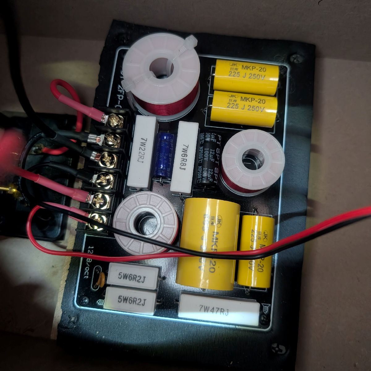
1) Two crossover boards mounted on rubber sheets over MDF bases. The rubber sheets serve as vibration control cushions.

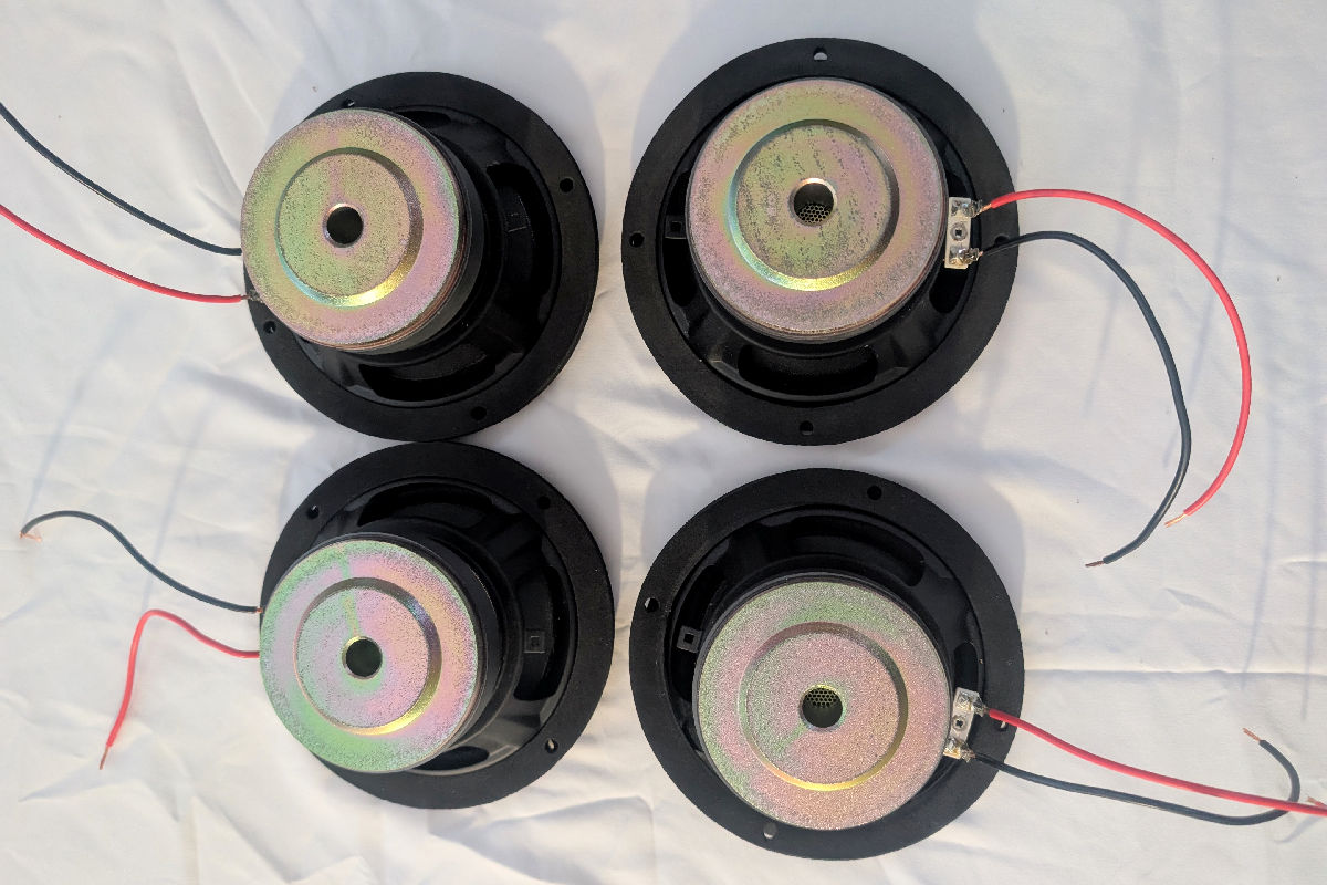
2) Four pre-wired 6.5″ custom woofers with rubber gaskets. Two of the woofers have slightly longer wires for ease of connection. These will be the lower woofers on the speaker cabinets.
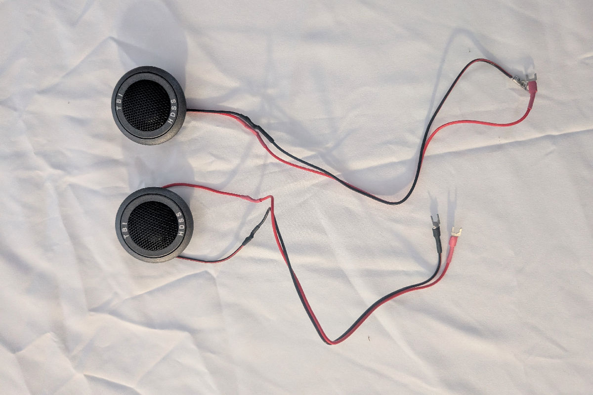
3) Two pre-wired 1″ soft dome tweeters.
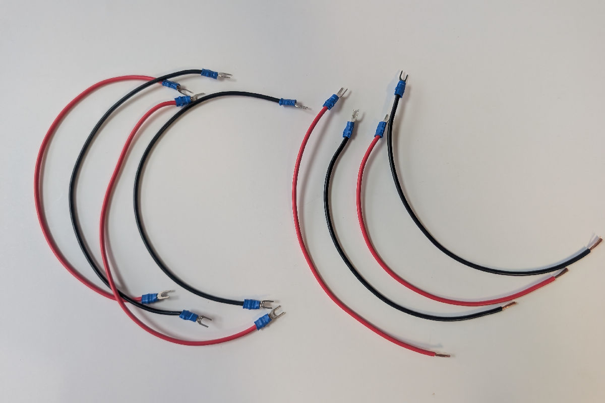
4) Eight pre-cut hook up wires, red for Positive and black for Negative:
- Four 12″ wires with spades on both ends for connection from the binding post + (red wire) and – (black wire) terminals to the + and – amp inputs on the crossover board.
- Four 8″ woofer extension wires, with spades on one end for connection to the woofer terminals on the crossover board, and with bare wires on the other end for connection to the woofer wires using the wire nut.
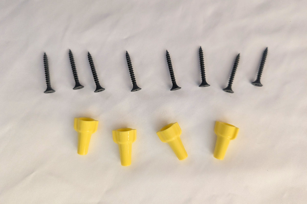
5) Eight wood screws for securing crossover boards onto the inside back of the cabinets, and four wire nuts. Four of the screws are pre-inserted into the drilled holes on the crossover board (as mentioned in Section B – Installing the Crossover).
Speaker Cabinet (To be Purchased Separately by the Customer)

Two speaker cabinets to be purchased by the customer directly from Iwistao through this link: https://iwistao.com/products/iwistao-3-way-speaker-empty-cabinet-passive-speaker-enclosure-15mm-high-density-board-labyrinth-structure-special-version.
The cabinets come in three finishes: Jujube Wood, Maple Brown, and Redwood.
These cabinets were customized to house the Gingko Audio MooVu™ speaker kit components. Be sure to order the specific model from the link provided.
Read the instructions on unpacking the Iwistao cabinets if you want to preserve the shipping box and packing material for reuse in future transfers or shipments.
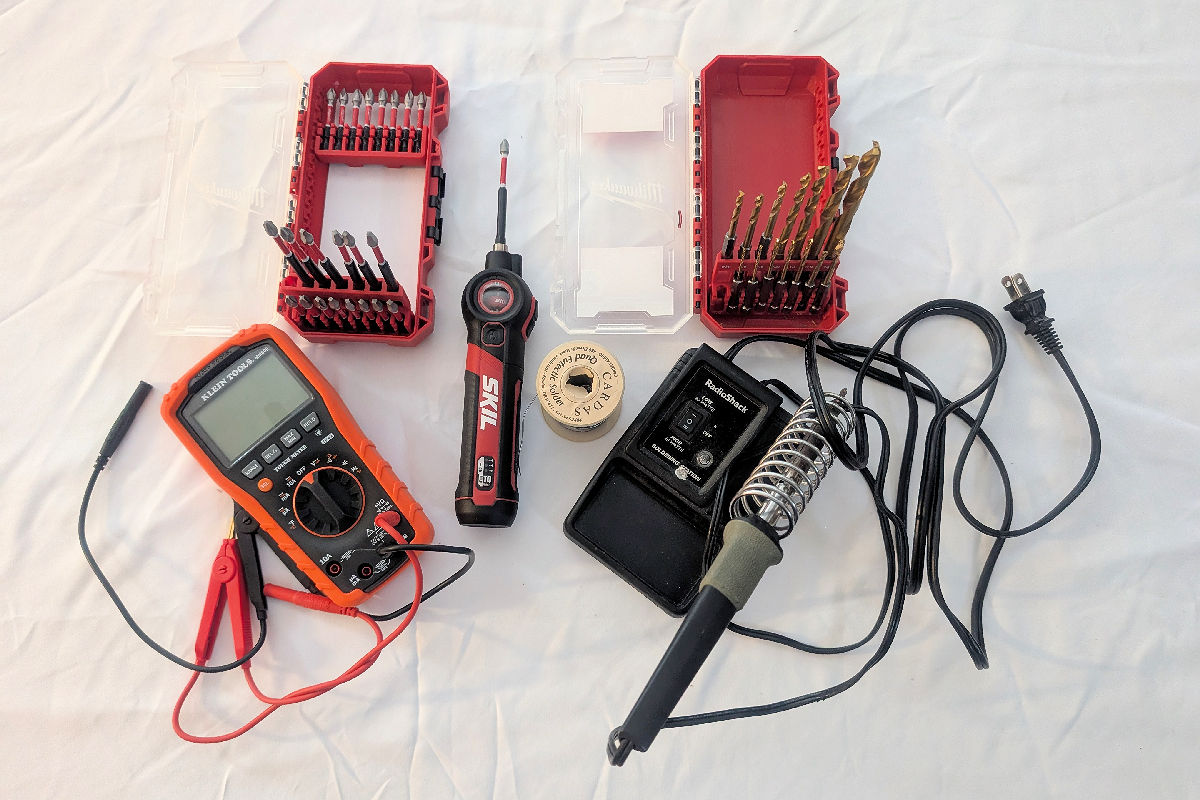
Tools and Other Supplies Needed for Speaker Assembly
- Phillips screwdrivers of different sizes and a long extension bit to reach inside the cabinet.
- Drill with bits of different sizes to drill pilot holes for the woofer screws.
- Solder gun with soldering wire (for customers who want to solder).
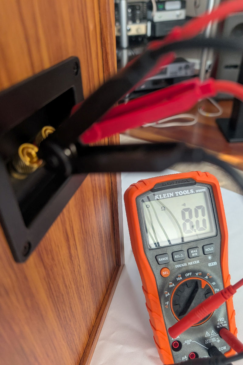
- Multi-meter to measure the impedance of the finished connections.
- Portable vacuum cleaner to remove sawdust from the cabinet (e.g., from drilling holes into the cabinet).
- Elmer’s Rubber Cement to coat around the tweeter housing to secure the tweeter in the tweeter hole.
- Batting material from a fabric store such as Poly-fil or other quality fiber fill, if the customer wants to augment the acoustic batting material that comes with the speaker cabinet.
Assembling the Speaker
The following instructions describes the process for one speaker. Repeat the steps for the other speaker.
A. Preparing the Cabinet
NOTE: Assembly should be done on a flat surface at a comfortable height for you to reach inside the cabinet to make connections. Before you start, cover the work surface with a soft cloth or blanket to prevent scratching the cabinet finish.
Step A.1: Lay the speaker cabinet flat on its front baffle with the driver openings facing down and the binding post assembly facing up.
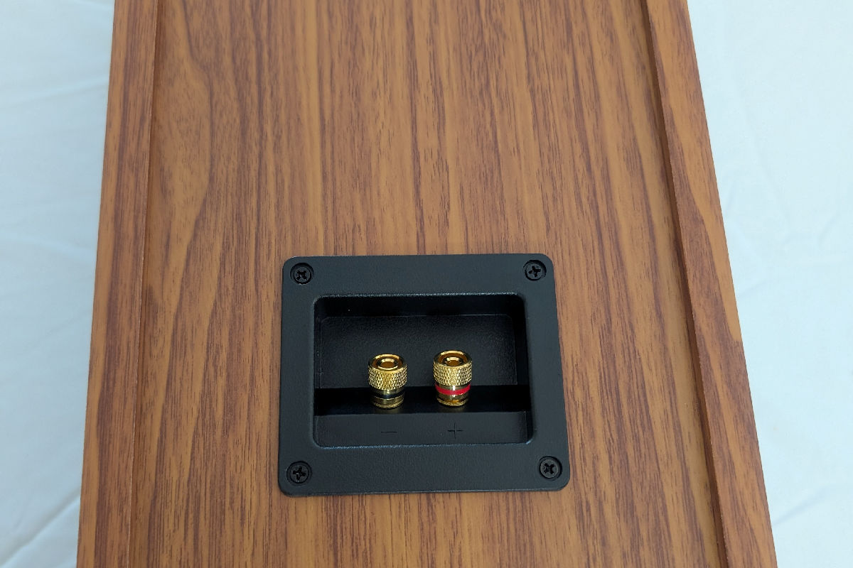
Step A.2: Unscrew the binding post assembly from the cabinet using a small Phillips screwdriver. Note the orientation of the binding post assembly before removing it from the cabinet to ensure that it is re-inserted correctly into the cabinet in Step A.4.

Step A.3: Attach two of the 8″ wires provided in the MooVu Speaker Kit (one black, one red) to the corresponding binding posts (black wire to black binding post, red wire to red binding post). For a more secure connection, you may opt to solder the wires to the tongues of the binding posts, as shown in Figure A.3.1. Otherwise, loosen the nuts on the binding posts, place the spades under the loosened nuts, and tighten the nuts to secure the connections (Figure A.3.2).
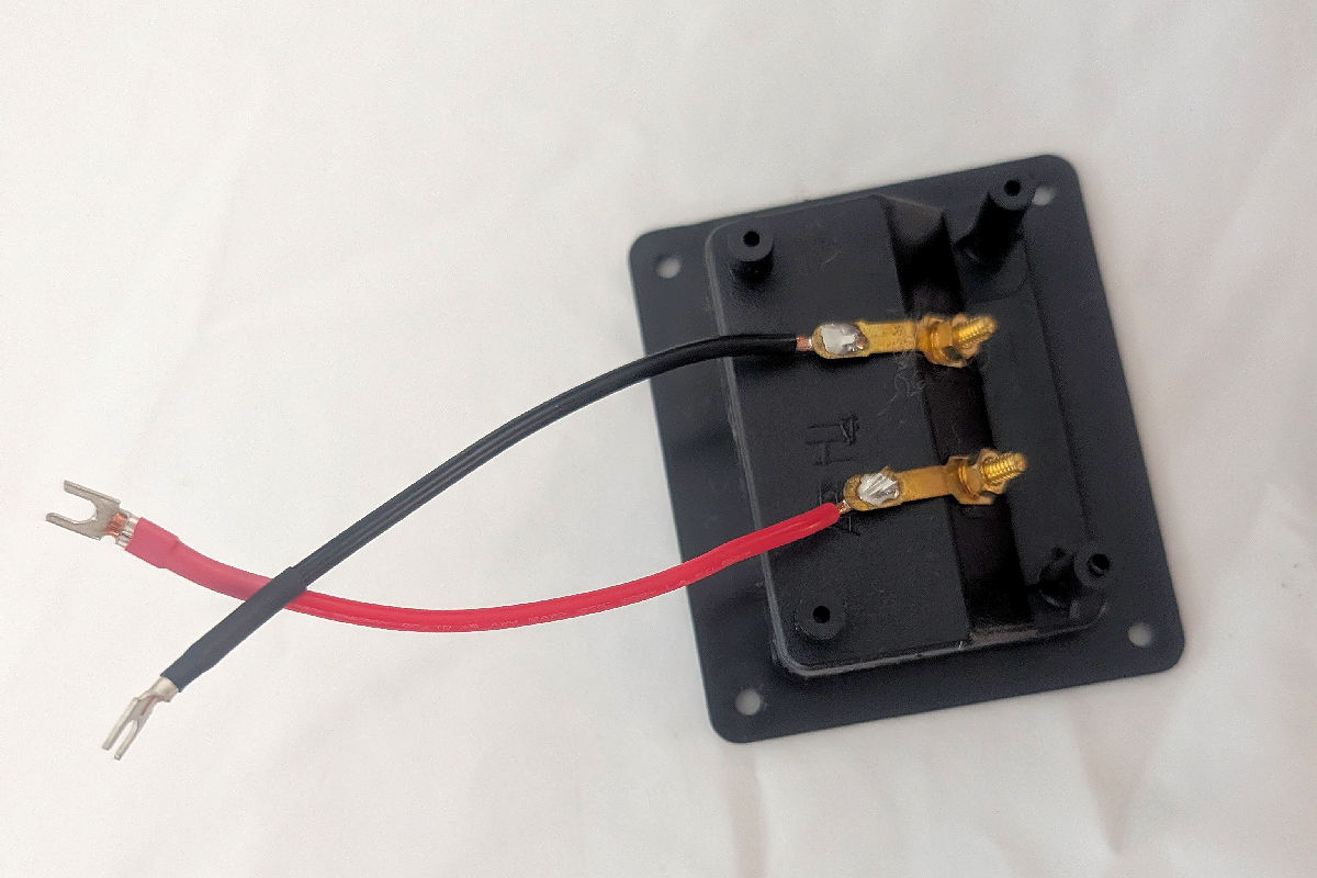
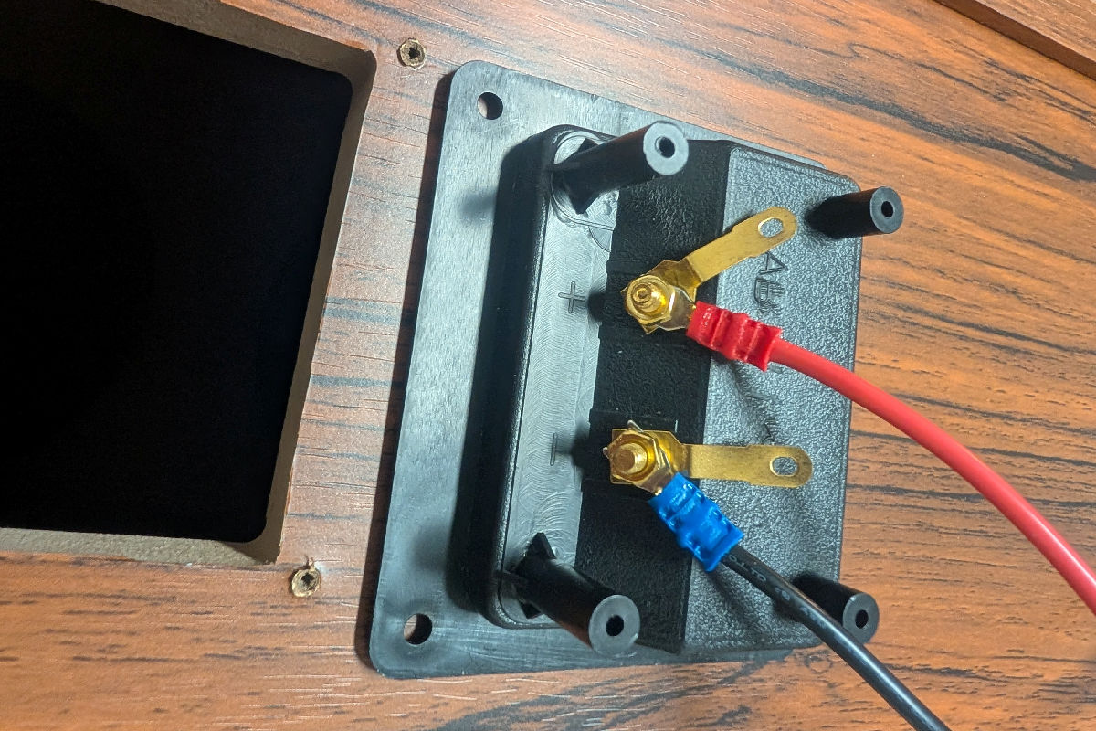
Step A.4: Re-insert and screw the binding post assembly back into the cabinet. Turn the cabinet over and lay it flat on its back with the driver openings now facing up.
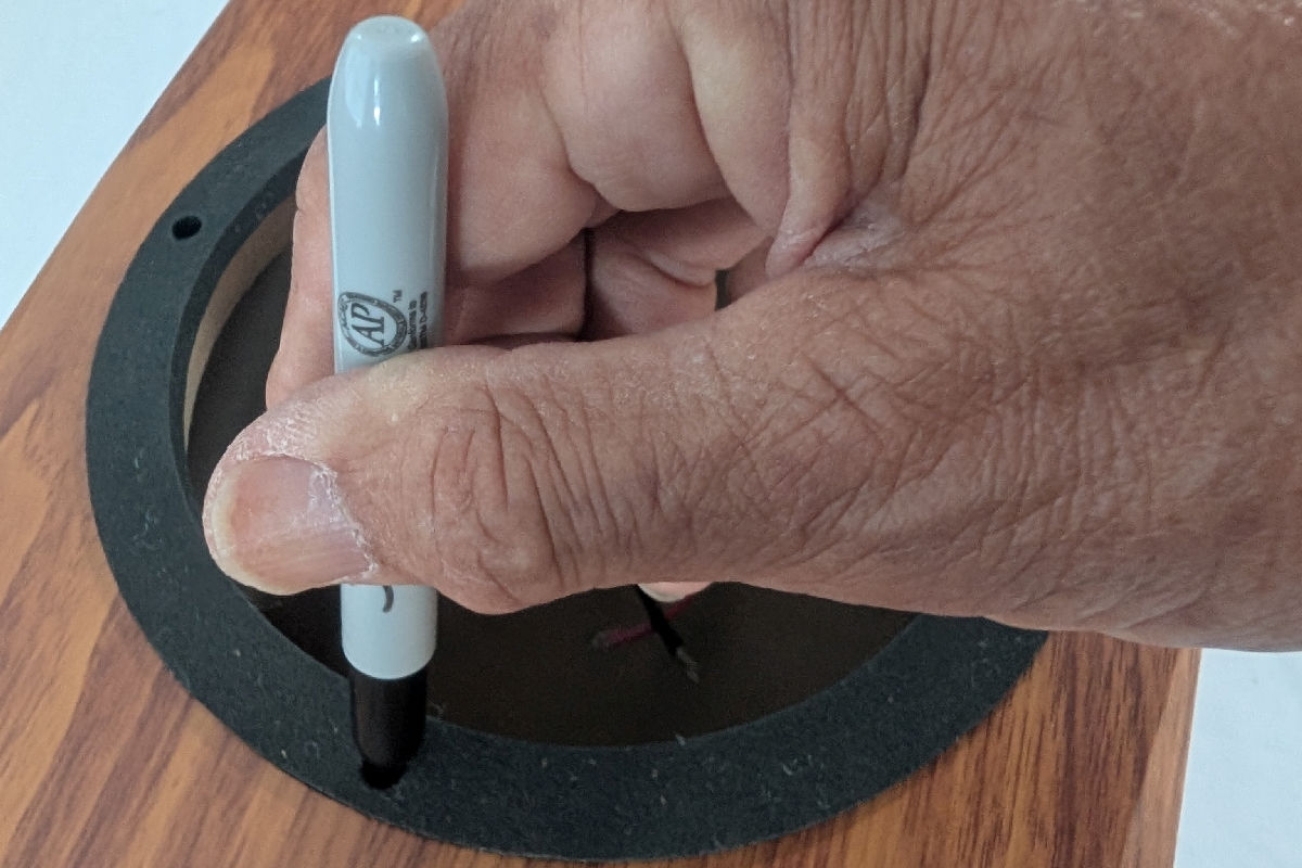
Step A.5: Lay the rubber gaskets onto the woofer openings and use a felt tip marker to mark the four drill holes on each of the flanges (Figure A.5.1). Make sure the drill holes for the upper and lower woofers match up, as shown in Figure A.5.2. For easier alignment, position the gaskets such that two holes on the upper woofer and two on the lower woofer form a straight line from the tweeter opening.
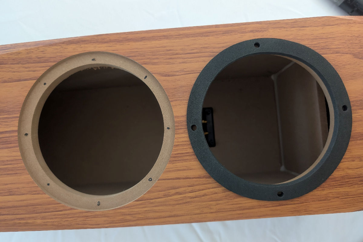
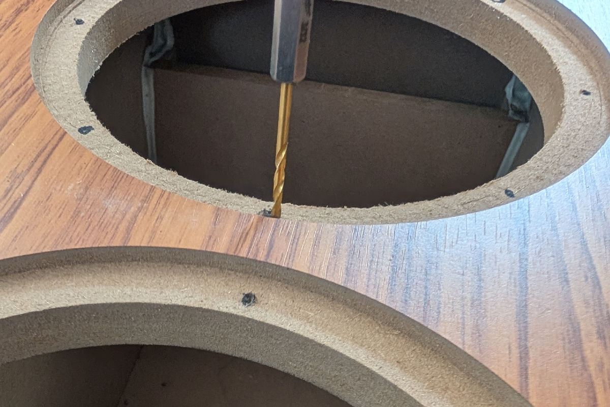
Step A.6: With a 7/64″ bit, drill four pilot holes for the hex head woofer mounting screws into the flange, using the marks made in the previous step. Use the portable vacuum to remove sawdust from inside the cabinet.
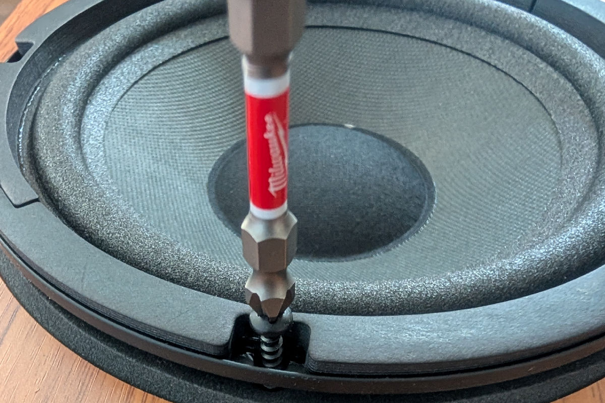
Step A.7: Place the (vibration-absorbing) rubber gasket onto the flange of the lower woofer opening, then place and attach the lower woofer using the provided screws. It is best to orient the wires toward the top of the cabinet to facilitate connection to the crossover later in the process. Be careful not to apply excessive downward pressure. If the screwdriver slips, it could damage the cabinet finish.

Step A.8: Insert the tweeter assembly into the tweeter opening in the cabinet, with the wires oriented toward the bottom of the cabinet and the letters TBI facing the top of the cabinet.
B. Installing the Crossover

The connection terminals on the crossover board are aligned as shown in Figure B above. With the terminals at the lower edge of the board, the correct order from left to right is: Amp IN (from binding post) + and -, Woofer – (- W), Tweeter, (-T), Woofer + (+W), and Tweeter + (+T).
- The IN terminals are for the wires from the binding posts. The Woofer and Tweeter terminals are for the woofer extension wires and tweeter wires, respectively. In installing the crossover, make sure the red wires are connected to the + terminals and the black wires are connected to the – terminals.
- The crossover board comes with four wood screws already inserted through the drill holes. Remove the screws prior to connecting the wires onto the Philips screws to avoid having the sharp ends poke your fingers in the process.
- It is good practice to install the spade ends of the woofer extension wires onto the Woofer terminals on the crossover board, the tweeter wires to the Tweeter terminals of the crossover board, and the binding post wires to the IN terminals OUTSIDE THE CABINET AND PRIOR to dropping the board into the top woofer opening. This is much easier than trying to connect them once the crossover assembly is already installed inside the cabinet.
Step B.1 : Reach inside the cabinet to find the tweeter wires and screw the tweeter wires to the + and – Tweeter terminals on the crossover board, making sure the red wire goes to the + terminal and the black/red wire goes to the – terminal.
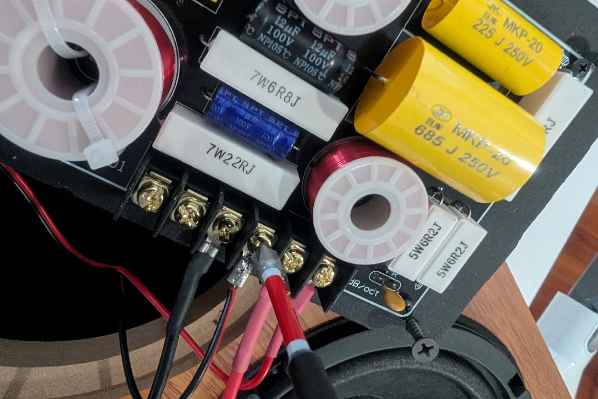
Step B.2: Screw the ends of the red and black woofer extension wires with the spades to the Woofer terminals on the crossover board, making sure the red wire goes to the + terminal and the black goes to the – terminal.

Step B.3: Screw the wires from the binding post assembly onto the Amp Input terminals on the crossover board, making sure the red wire goes to the + terminal and the black wire goes to the – terminal.
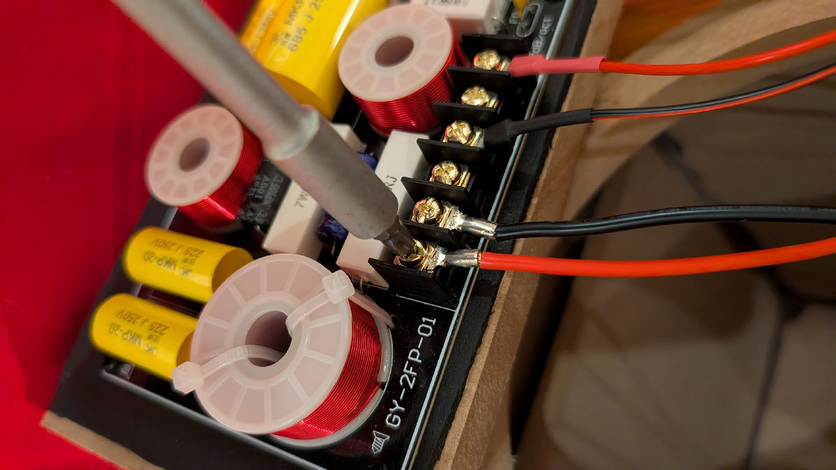
Step B.4: (Re)insert the wood screws into the pre-drilled holes on the crossover board before dropping the crossover board through the cabinet opening for the top woofer. Place the crossover board such that the bottom edge near the connection screw terminals is about ¼” from the top edge of the binding post assembly.
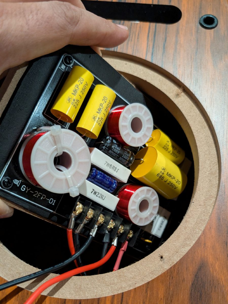
Step B.5: Tighten the wood screws onto the back of the cabinet. The length of the wood screws will ensure that the crossover board is secured to the back of the cabinet without going through it.
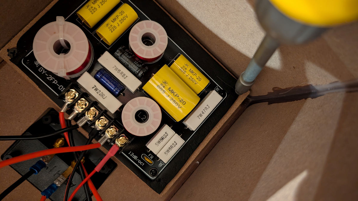
Step B.6: Place the top woofer face down over the tweeter with the wires oriented toward the bottom of the cabinet to facilitate connection. Be sure to place the rubber gasket onto the woofer or the flange BEFORE connecting. Use the wire nuts to secure connections between the red extension wire, the red wire on the top woofer, and the red wire on the bottom woofer. Similarly, secure connections between the black extension wire and the black wires on the top and bottom woofers.
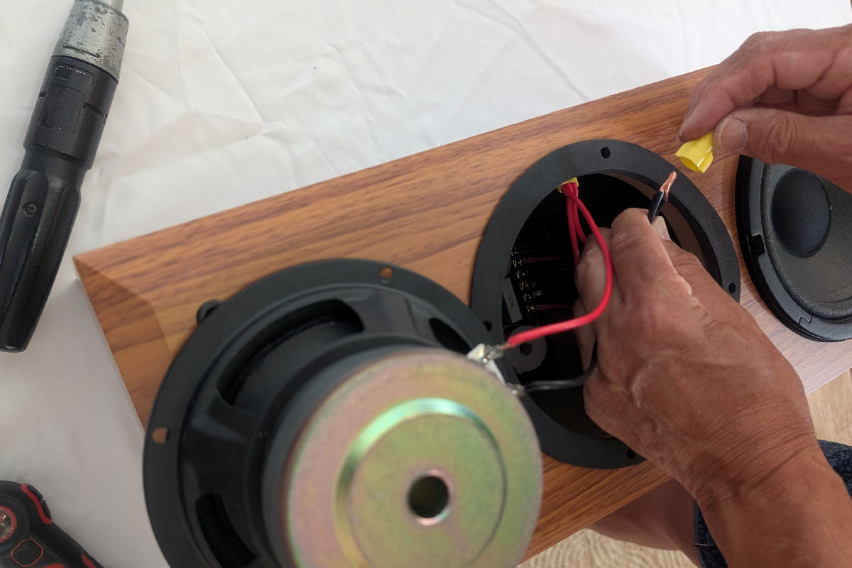
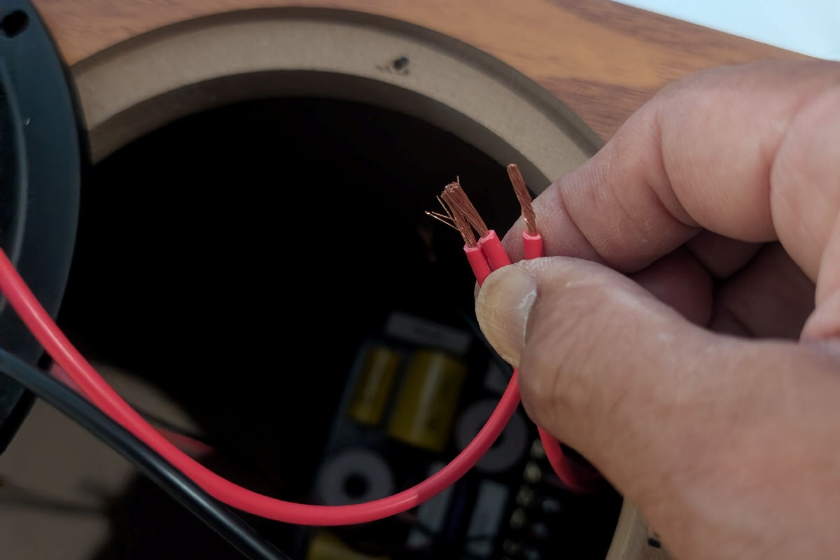
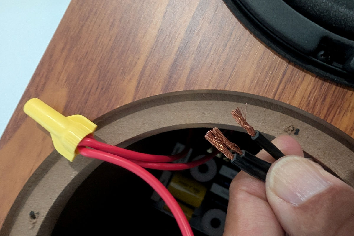
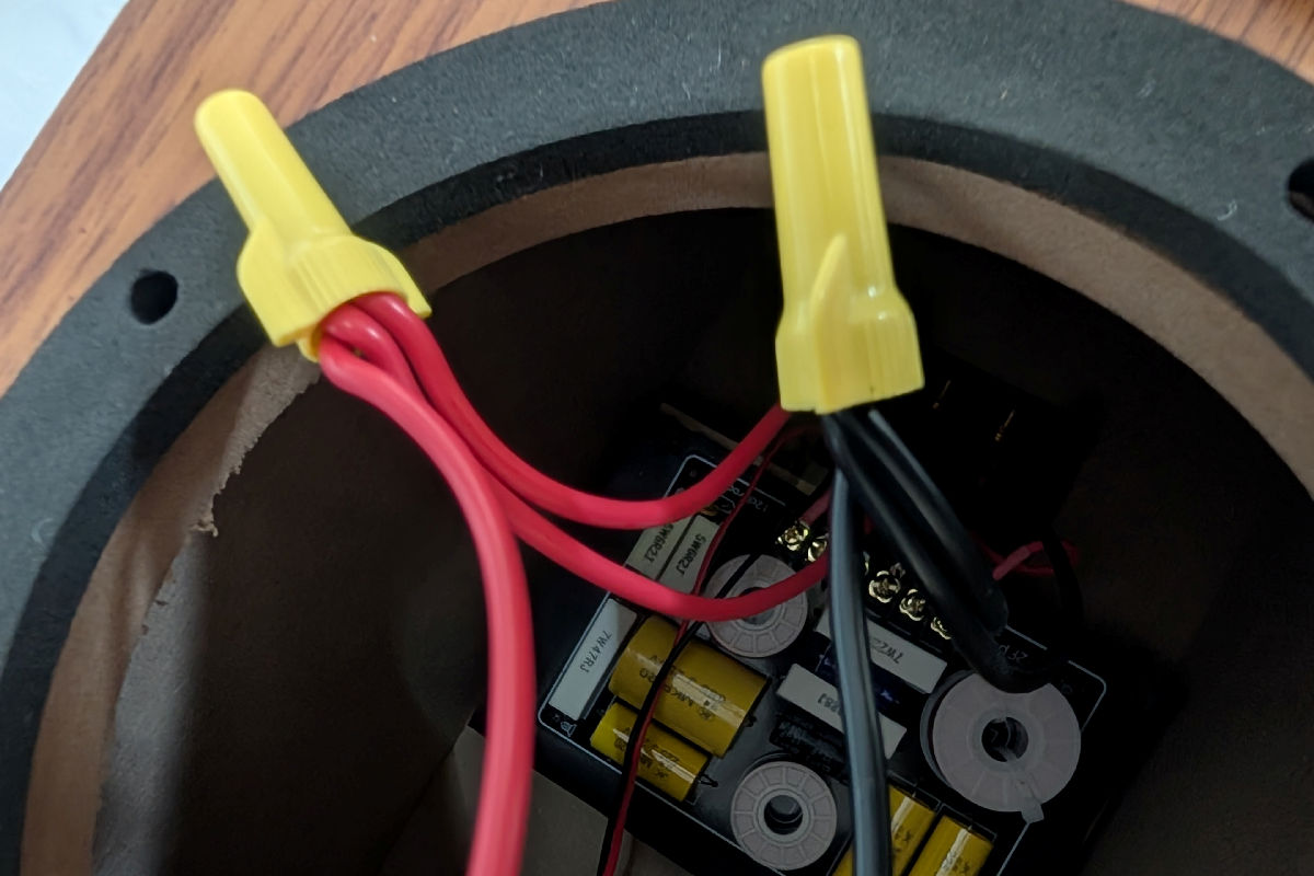
Step B.7: Double-check that all connections are correct and secured.
C. Completing the Installation
Step C.1: Stuff the acoustic batting that comes with the cabinet into the top and bottom section of the cabinet, first behind the tweeter and lower woofer, then on top of the crossover board. Keep all the wires away from the woofers and crossover board by placing the batting material in between these.
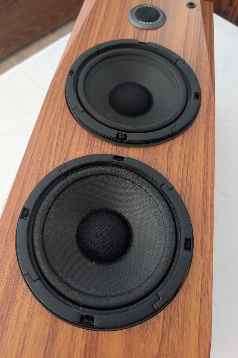
Step C.2: Place the top woofer over the top woofer opening and secure it onto the cabinet. Be sure to include the rubber gasket under its flange and align the top woofer so that its drilled holes are symmetrical with the lower woofer’s holes for better aesthetics.
Step C.3: Use the multi-meter to measure the resistance between the + and – terminals of the binding posts. It should read about 8 ohms.
Testing and Using the Speakers
Once both speakers are assembled, hook them up to an audio system to test:
- To test the drivers, gently touch the woofers while music is playing to make sure they are moving.
- Place your ear next to the tweeters to make sure they are playing the higher frequencies.

Once you are happy that the speakers perform as expected, gently pull the tweeter assembly out of the tweeter holes without damaging the finish and put some rubber cement on the outside edges of the tweeter housing before re-installing for a more secured fit.
The speakers will require about 100+ hours of break-in. Play a track of pink noise through them over several days before critical listening. Enjoy!
Recommendations for Audio System Components
To drive Gingko Audio’s MooVu speakers, we recommend an inexpensive Class D Bluetooth amplifier like the Fosi BT20A Pro using Bluetooth streaming from your phone. This Fosi amp also has a pair of RCA analog inputs for another source such as a turntable/phono preamp or a CD player.
For speaker cables we recommend something comparable to these cables from VeraFi Audio.
We also recommend placing the MooVu speakers on a pair of 20” high stands, like these Vanguard stands.
For best results, you may choose to use the Gingko Audio ARCHs or some other vibration control feet under the stands to isolate the speakers and stands from the floor.